As should be obvious from my previous writing I do have some love for delta loops. Although they are big and (to some) ugly they do have certain advantages:
- Inexpensive - lots of performance per dollar
- Multiband - on harmonics
- Easily configurable for any linear polarization - vertical, horizontal or in between
- Can be matched to typical transmission lines with a quarter-wave transformer - doing this does unfortunately remove the multiband capability
- Omnidirectional when configured for vertical polarization
- Like any full vertical (dipole or loop) it is a decent DX performer even at low heights
- Requires only one support mast, although it should be non-conducting if vertically-polarized
- Broadband - low SWR across the band when matched to 1.0 SWR at resonance
- Loops are quieter in rain, snow and low humidity since there is no corona effect off the ends
- If visible to non-ham neighbours it is often perceived as an eyesore
- There are ropes going everywhere, both to hold the shape of the loop and to guy it and its mast
- Heavily dependent on ground quality when vertically-polarized (as for any vertical) for far-field performance
- Can be fragile if not well designed and constructed
 For this article let's put all this aside and just design the thing. No one has to use it after all, and that includes me.
From the adjacent EZNEC antenna view it is a somewhat unusual looking design. There are nested loops cut for 20, 15 and 10 meters.
You'll see that there are two feed points: one each on the 15 and 20 loops. They are fed with 70Ω λ/4 transformers (RG-6/59/11) to match the high loop impedance to 50Ω. There is no feedline to the 10 meters loop since it will be parasitically fed. I'll come to that in a moment.
If you're familiar with quad beams you'll likely know that they are fed at a common point, where the loops for each of the driven elements are brought together. This work since the impedance of a quad beam is typically very close to a 50Ω match. That doesn't work in the present case since this is not a beam and matching is required. I did try various techniques but none worked well. Since I am pretty much swimming in coax I decided to go with more than one transmission line.

 I mentioned how 20 and 15 are matched, but 10 is special. The 20 loop resonates harmonically on 10 but not where we want it. It resonates well below the band. Also, that λ/4 transformer for 20 is now a λ/2 on 10. What this does is leave the impedance unchanged; it is equivalent to making a full circle on a Smith chart. That isn't what we want.
So what I did was, in effect, make this a 2-element parasitic array on 10 meters, tuning the inner loop such that the array resonates where I want it. This has several affects: the impedance drops to near 50Ω at resonance (which the 20 meters transformer leaves alone); the pattern gets more complex, but does not become a unidirectional beam; and, the bandwidth is reduced due to the increased Q.
As usual I cut my antennas for CW. I also have no interest in 10 meters above about 28.6 MHz. You can adjust the antenna to your operating preferences.
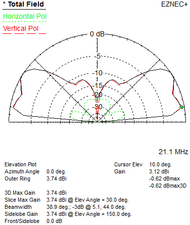 The 20 and 15 loops are fed 1/4λ from the apex (~25% of leg length from the bottom) to make the antennas
vertically-polarized and omnidirectional (within 3 db). Although this is covered in an
earlier article, the elevation pattern for 20 meters is posted here. Although ground loss is ~3.5 db the gain at 10° is an impressive 1.5 dbi. That isn't possible for a dipole at the same height over suburban ground.
The 20 and 15 loops are fed 1/4λ from the apex (~25% of leg length from the bottom) to make the antennas
vertically-polarized and omnidirectional (within 3 db). Although this is covered in an
earlier article, the elevation pattern for 20 meters is posted here. Although ground loss is ~3.5 db the gain at 10° is an impressive 1.5 dbi. That isn't possible for a dipole at the same height over suburban ground.The pattern for 15 is similar. Ground loss drops to 2.8 db and the 10° gain rises to 3.1 dbi. This is quite good.
The actual maximum gain for both 20 and 15 are in higher angle lobes. This makes the antenna usual for domestic contacts, which in my case would only matter during contests if at all. Unlike a low dipole there is a deep null at high angles. This is not too interesting on the high HF bands but it may help remove some domestic QRM while chasing DX.
 For purposes of SWR and pattern the
ground is modelled on the poor side of medium, typical of suburban areas. The
antenna (bottom of the 20 loop) is set at 10 meters. This would put the apex at 16.3
meters. If I build it I will drop it a bit to keep it under the 15 meter height threshold that requires undesirable city (Ottawa) policy conformance.
For purposes of SWR and pattern the
ground is modelled on the poor side of medium, typical of suburban areas. The
antenna (bottom of the 20 loop) is set at 10 meters. This would put the apex at 16.3
meters. If I build it I will drop it a bit to keep it under the 15 meter height threshold that requires undesirable city (Ottawa) policy conformance.The pattern on 10 meters is not ideal due to being both parasitic and having one element 2λ long. Of course there is additional gain in some directions, but also less in others. The antenna is fixed so I would just have to live with it as is. I am not too concerned since 10 will soon (2014) begin to decline in importance as the current solar cycle declines. It's a compromise. I could always fill the "gaps" with another antenna.
 The surprising thing about the elevation pattern on 10 is that it is horizontal off the ends (antenna plane). That's the effect of driving it from the 20 loop. Even so it does well at low angles, equalling the gain on 15. The high angle radiation is less useful for DX but will come in handy for aurora and sporadic-E openings. Ground loss is a little over 1 db, which is negligible.
 The antenna is not omnidirectional on 10. Unlike 20 and 15, at most elevation angles the gain is higher off the ends than broadside. The pattern shown here is for 10°, which is most pertinent for DX. The differential between the gain off the ends and broadside is larger at higher angles. Although this isn't perfectly aligned with my design objectives the compromise is acceptable.
Some construction details follow.
The loops do not have to be perfectly concentric but should not snuggle up to each other. I confirmed this to some extent through modelling, but it is a lot of work to be comprehensive and certain. Therefore it is better to err on the side of making the loops close to concentric. As shown here the separation between the 20 and 15 loops is 141 and 70 cm at the apex and bottom, respectively. Between the 15 and 10 loops the separation is 61 and 40 cm at the apex and bottom, respectively.
The antenna is cut for CW so the SWR climbs towards the high end of the bands, particularly on 10. The model wire is 12 AWG THHN copper. Increasing the gauge to 10 is a good idea for a 40 meters loop, but 12 should be ok here. The bottom of the outer loop in the model is wire, however I would build it using aluminum tubing of about 25 mm diameter (1-inch). I have this already so the cost of aluminum tubing is not relevant. The tube will lower the total 20 meters element length a small amount.
Element lengths are as follows, with 1/3 of the total in each of the 3 sides (equilateral triangle):
- 20 meters: 21.78 m
- 15 meters: 14.47 m
- 10 meters: 10.98 m
Although the interior angles don't have to be exactly 60°, staying close (equal side lengths) will keep the performance in line with the design. Just ensure there is tension on the wires so they don't sag, even under temperature changes (metal shrinks or expands in accord with the temperature) and ice and snow loads.
The apex of each loop is tied to the mast, which must be non-conducting. Fibreglass is a good choice since the antenna stands fairly tall and must be tough to survive the weather, and it can be guyed. When mounted at some height a metal mast or tower can be used under the fibreglass mast provided it doesn't get close to the antenna bottom centre, since it is a high-impedance point. Keep the separation at least 1/2 meter.
No comments:
Post a Comment
All comments are moderated, and should appear within one day of submission.