 For those interested in why I chose to go with a delta loop for 40 meters please refer back to this earlier article on vertically-polarized antennas. That article and the earlier ones it links explain it, so I won't bother to repeat all of that here. All that I'll repeat here is the elevation pattern of the antenna at 7.050 MHz. This is in both broadside directions. In the plane the gain the antenna it is -3 db from the peak. The pattern is almost perfectly symmetrical, only slightly distorted by the presence of the tower and steel mast.
From deep inside my expansive junk box I retrieved a 40 meters delta loop and ¼-wave transformer. Like many hams I tend to not throw out stuff so almost all of my previous antennas are packed away somewhere. I chose to reuse it rather than spend the time making a new one since it's certainly good enough for my present needs.
This particular antenna was the first at this QTH, and went up in the air soon after arrival in October 1984. First it was supported by a temporary guyed mast made of storm-salvaged aluminum boom and element tubing. The next year it went onto the 20 meters tall tower I put up. It came down around 1990 when I replaced it with a switchable 2-element wire yagi. Looking back, the delta loop and 100 watts did a great job putting lots of great world-wide DX into the logbook.
This is an old antenna, and its age shows. The insulation on the 12 AWG stranded copper wire is not UV-resistant. Originally beige its colour ranges from off-white to dark brown. It is also cracked and there is some copper corrosion visible when the insulation is stripped. Despite these shortcomings, well, copper is copper. It doesn't have to look pretty and if it corrodes further that is not a problem for the next season or even a few years. The important point is that I didn't have to build a new delta loop from scratch.
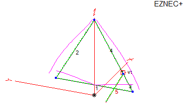
The length of the antenna puzzled me. It measured 40.1 meters, which is substantially less than the 43.3 meters that my EZNEC model requires for resonance at 7.050 MHz. Since it's easy enough to add wire to it later I just shrugged away the mystery and put it up as is. The only modification I made was to moved the tie points so that the feed was per the model for vertical polarization and omnidirectional pattern. This is 25% up the vertical leg closest to the house, or ¼-wave down from the apex. The original antenna was fed at one of the bottom corners.
I tried to make the model reasonably comprehensive so I included the tower and metal part of the mast. I skipped adding in the TH1vn since earlier modelling showed that the interaction was negligible. That made the length disagreement more of a mystery.
Much to my chagrin the antenna resonated at 7.6 MHz. I can only surmise that when originally tuned there was interaction between the delta loop and the all metal mast. On that mast the antenna apex was secured directly to the mast top, with only the wire insulation separating them. The apex, even with corner feed, is still at a high impedance point on the loop so the coupling may have lowered the frequency of resonance, thus requiring a shorter loop length. In the present configuration the apex is tied to the top of 3.4 meters of fibreglass mast so that coupling is no longer present.
I made the adjustment in two stages, finally reaching resonance at 7.050 MHz with the addition of 3.4 meters of wire. The tie points were shifted in proportion so that the loop remains roughly equilateral. This makes the final loop length 43.5 meters. This is spookily close to the 43.3 meters found with EZNEC. It gets better. Take a look at the following SWR curves.


Either this is a great model (and modelling software) or it's all just a happy coincidence. It is rare to have such excellent agreement between a model and the real antenna. There are just too many sources of error that can creep in, such as insulation dielectric constant and thickness, ground conductance, nearby metal, accuracy of the ¼-wave-transformer, tower interaction, etc. The SWR/Power bridge is a pretty good one -- Daiwa CN-620B, almost 30 years young -- so I made the measurements with it rather than the comparatively inaccurate one in my KX3 rig (it often measures lower than reality).
If you read the previous article on the mechanical design you may have noticed the lack of a common-mode choke on the coax. This is deliberate. The weight of a coax choke made of RG-11/U (¼-wave transformer) is quite heavy and the loop already deflects quite a bit as it is. Instead my plan is to place the coax choke at the other end of this section, in the main run of RG-213/U. This can be done because the ~7 meters long run of RG-11/U appears as a high impedance wire on 7 MHz. This assumes the choke has a high impedance so that the electrical length is approximately the same as the physical length.
To test this out I modelled the RG-11/U as a thick, insulated copper wire in the EZNEC model. I tried it with the coax running orthogonal to the antenna plane and at more realistic drooping angles.
The current plot shown here is with the coax running in a straight line downward toward where it would meet the actual choke. The real coax curves (as does any suspended cable). The current on the coax exterior remain very small even at greater angles. The modelled affect on the pattern is no more than about 0.1 db. However, if you try this don't push your luck and eliminate the choke entirely. That will certainly mess up the pattern, bring RF into the shack and increase the risk of RFI.
There really isn't much more to say about the antenna design and model. It's pretty simple, and it works. I don't have a suitable comparison antenna on 40 meters so all I can do is put it on the air and try it. I have done that now for a few evenings. Considering that I am running QRP (10 watts) I am pleased with its performance. It appears to work equally well in all directions and I was competitive in several pile-ups. Examples include ZD8O, ZB2FK. As always there are some stations that I cannot work, even when they have no callers. On the other hand I notice that many other callers find themselves in the same predicament. Either those DX stations have a lot of QRM or QRN or, perhaps more likely, are alligators with a "mouth" much larger than their ears.
There are some interesting DXpeditions on at present, so I have some opportunities during November to put the loop to the test. My calls to K9W (Wake I.) and others on 40 meters have not yet resulted in contacts. With QRP it is generally better to wait a few days until the big guns make their contacts and thus reduce the competition for the rest of us.
 Although I don't have a comparison antenna what I can do is model alternatives. Since I excluded verticals both short and long for performance shortcomings in my earlier modelling experiments I instead modelled an inverted vee. I chose the same support configuration as used for the delta loop, so that its apex is also up 15 meters and it goes to the same tie points. Doing so results in an interior angle of about 130°, which is quite good. I could do even better by raising one end to the chimney (up 8 meters), although the difference is minor. This also reduces the little omnidirectionality an inverted vee offers.
In the broadside elevation pattern I show the gain at the same angle as where the delta loop peaks. It is only a little more than 1 db better. Although the ground losses in the inverted vee are lower, at this height most of the radiation is wasted at high angles. This is not only useless for DX it can also increase the QRM from domestic stations, which can be particularly troubling during pile-ups and contests. Off the ends, as one should expect, the inverted vee performs poorly in comparison to the delta loop, down 5 to 10 db or worse.
An inverted vee is not quite as broadband as a loop but it still adequately covers the 40 meters band when cut for CW. With a 7.050 MHz resonance the SWR rises to 2.5 at 7.300 MHz.
I will likely follow up in the future as I get more time in with this antenna, and especially with the CQ WW weekend coming up at month's end. One thing I want to try is some evening gray-line openings to Asia and Australia, particularly Japan, which are coming up very soon on the calendar.
I expect that my next article will follow up on the mechanical design. Those in the Ottawa area will know that we just had a day-long bout of high winds, with gusts up to 90 kph. I wasn't expecting that, so I thought I had the luxury of time to finish strengthening the extended mast on the tower. Everything survived the wind but that is no excuse to put off this work any longer.
No comments:
Post a Comment
All comments are moderated, and should appear within one day of submission.