Here it is fully built, ready for installation on the 14 meters tall tower:
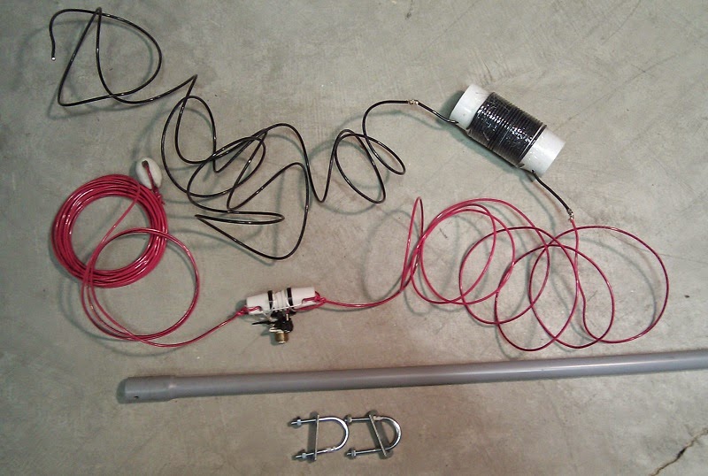
Starting from the upper left and proceeding clockwise:

- 3.02 meters wire (measured to centre of coil)
- 11 μH coil
- 3.75 meters wire (measured centre of coil to centre of feed point insulator
- 1.5 meters of ½" Schedule 40 PVC pipe, with 2 U-bolts
- Centre insulator with SO-239 feed point
- 6.7 meters wire (measured from center of dog bone insulator), plus 30 cm extra for trimming
- Egg insulator bottom termination
Another change I made was to place the sloper and tower in the same plane, so that the sloper runs directly away from the tower towards the northeast. This gave the best forward gain (no surprise). In the original model I offset the sloper so that it started 2 meters to the tower's side and ran parallel to the 80 meters half sloper. The new arrangement reduces variables for this experimental antenna. The 80 meters half sloper wire was pulled out of the way, at least temporarily.

Symmetry is in any case a mirage since the antenna halves interact unequally with the tower and ground. A common mode choke tuned for 40 meters is made by coiling 12 turns of RG-213 (air core, 7" diameter) on the transmission line, positioned about 5 meters from the feed point. This arrangement avoids feed line radiation while allowing the weight of the coil to be supported by the tower rather than the antenna.

The coil is wound on a 5" length of 2" O.D. plastic pipe cut from a remnant left over from the installation of a built-in vacuum cleaner. It's a bit soft but strong enough for the job. Four holes are drilled along a line, 1" and ⅜" from both ends. The coil length is 3", the distance between the inner holes. The insulated 12 AWG stranded wire I used is not ideal for the application but it was handy and the turns spacing was a perfect fit. By threading through the holes as shown ensures that the wire is mechanically stable. A bit of plastic wrapping tape keeps the outer turns of the coil from spreading outward.
Coil ESR (equivalent series resistance) can be somewhat high and still achieve negligible loss. This is generally true of loading coils on a single element antenna. More care in coil design and construction is recommended for traps and for loading coils in yagis. As built the coil can probably handle a kilowatt without excessive heating. However this cannot be guaranteed without testing.

 The feed point is bit odd looking. Two tie wraps secure the wire ends, which are soldered to the SO-239 centre pin and solder lug. The lug is secured with a stainless steel screw and nut. The synthetic twine and third tie wrap hold the connector to the insulator so that the weight of the coax doesn't stress the soldered connections.
At right you can see the PVC pipe angled upward and secured to the uppermost X-brace on the tower. This places the far end of the pipe at about tower height (14.1 meters) and 1 meter distance when tension is applied to the antenna and simple rope stay.
The 80 meters half sloper was released from its bottom anchor and left dangling vertically for this experiment. The model shows some negative interaction so I wanted to remove that influence for the present. If you're interested this photo of the half sloper feed point complements the one shown in the 80 meters half sloper article.
 For now the ground anchor for the 80 half sloper is used for the 40 meters sloper. I've included a photo of the anchor here since I only showed the temporary anchor in the 80 meters half sloper article. The stake is 42" long, with 12" buried adjacent to the retaining wall and then nailed for lateral stability. A screw at the top rear acts as a retainer for the nylon rope holding the bottom of the antenna. It works remarkably well considering its simplicity, able to take a lot of tension.
Modelled performance
As stated above and in earlier articles my objective is a 40 meters antenna that does better toward Europe (northeast direction) than the inverted vee. It is forward gain I want, with rejection of signals from other directions not a priority of the design. However some rejection (F/B, etc.) comes along for free since if you add gain in one direction it must come from other directions -- conservation of energy.
From the EZNEC antenna and current view of the sloper at the start of this article you can see that the sloper has a deliberately selected separation from the tower at the top. The induced current on the tower shows that it acts as a parasitic element, a weak reflector element which is not specifically tuned for the purpose. The modelled gain due to the tower is only ~0.7 db. The 80 meters half sloper is rotated 90° in the model since there are interactions that the model suggests would result in up to -1 db loss of forward gain on 40 meters.

The diagram to the above left is extracted from an ARRL document that plots measured elevation angles for various paths and frequencies. It is data like these that I relied on to establish 10° as the standard of comparison between antennas designs for DX paths on 40 meters.
The gain of the sloper only exceeds that of the inverted vee below 19° elevation. At 10° elevation the difference is 2.2 db in favour of the sloper. The sloper should reject (have less gain) than the inverted at most other elevation angles and directions. This reduces QRM from North America, which can be helpful at times. The modelled ground loss of the sloper is -4 db for medium ground. The inverted vee has almost negligible modelled ground loss.

The feed point impedance is a little high for 50 Ω coax but good enough for my purposes. It turns out that the measured SWR of the installed antenna has a similar curve but is acutely sensitive to the bottom end's distance above ground. Before trimming the SWR dipped to 1.4 at resonance, then rose to a minimum of 1.9 when resonant at the bottom end of the band. The KX3 seems happy with this.
Measured performance
The antenna was hooked up just before sunset, which allowed for immediate feedback on actual antenna performance. It was with some anticipation that I hooked up the coax, measured the SWR and trimmed to antenna to resonance. Then I listened to the European station that were just beginning to roll in. I switched back and forth between the inverted vee and sloper, comparing receive levels (including SNR) for various DX and domestic signals.
Let me be blunt: I was disappointed. The F/B was as expected but not the forward gain. Europeans were consistently stronger on the inverted vee than on the sloper. I stepped away from the shack to wait a couple of hours. It is often the case that elevation angles at sunset can be higher because absorption in the D layer of the ionosphere continues for a while due to the sun still shining at those altitudes.
After waiting the results were unchanged. Even on the longer paths in the same direction (4X, 4L, etc.) I saw the same thing. The inverted vee was consistently ~1 S-unit better. The atmospheric noise level was nearly the same on both antennas, suggesting that something other than higher ground loss on the vertically-polarized antenna. What was going on?
Let's look at what I actually measured. Keep in mind that I did not go for precision in these measurements, which would have required some sophistication in test equipment or hooking up the I-Q output to a PC and writing some DSP software. I know how to do that but I don't believe it's worth the time investment.
- System loss: Two major and easily modelled losses are near-field ground loss and transmission line loss. With medium ground the modelled ground loss is -4 db. Transmission line loss of 150' of RG-213/U at 7 MHz and a 1.9 SWR measured at the source is -0.9 db. Total system loss is therefore -4.9 db. This compares to -0.8 db for the inverted vee. The relative system loss of the sloper is therefore -4 db. This will affect both noise and signal, but not SNR since the atmospheric noise at 7 MHz far exceeds receiver noise. Coil loss (ESR) is not a factor, which was confirmed by elevating it to an unnatural level in the model.
- SNR: I picked a clear frequency (mostly near 6.990 MHz) and set the receiver bandwidth to give a noise level of about S-9. Tests were only done when there was no man-made QRN (typically lighting system power supplies), and were done at a variety of times over two days. Atmospheric QRN here in November is low and there is little chance of electrically-active storm systems that would favour one antenna due to directionality or polarity. The averaged comparison has the inverted vee at just under 1 S-unit more efficient than the sloper.
- F/B: The modelled F/B of the sloper is in the range of 10 to 15 db. I tested this with many stations on the air and estimated F/B using only the S-meter, with signals near the standard calibration point of S-9. It varied by station (direction and path angle) but was borne out overall. This confirms the model in that the tower is acting as a weak reflector parasitic element.
- Gain: Conditions to Europe on 40 have been good much of this week, providing many test signals. To Europe, west Asia and the Middle East (all within the antenna's main lobe) the sloper did worse than the inverted vee on every station. The difference ranged from 1 to 2 S-units. Since the noise level (see above) typically declined by less than 1 S-unit on the sloper this resulted in poorer SNR for the majority of signals on the sloper. Measuring relative levels was complicated by Faraday rotation since the period of rotation can be slow at 7 MHz and the antennas are of opposite polarity. When one antenna reaches peak amplitude on a particular signal the other antenna is usually at minimum amplitude.
Was this experiment a failure? No! The antenna did not meet expectations but it did so in an interesting and instructive manner. I now know something I didn't know before. That knowledge is valuable. Too few hams have, or take, the opportunity to compare antenna performance. Yet antenna performance is the major factor between doing well or poorly, whatever your operating pursuit, for the typical suburban amateur with a small station or with QRP. High power obscures antenna problems at many stations.
There is also the psychological factor, where many hams convince themselves that the antenna they built or bought must be doing well since to consider the alternative calls into question their decisions or abilities. Better not to compare and remain blissfully ignorant of the truth. I think this explains why so many hams claim to be happy with their low-performance multi-band commercial "no radials" verticals.
I prefer to know the truth even if the truth hurts. So I experiment, measure, assess and learn to do better. Every experiment is a successful experiment to my way of thinking. None of which says that this sloper doesn't work, only that it doesn't work as well as I'd like. I think that's important to know and, if possible, to know why.
Now it's time to speculate on what might be going on and what that might mean.
- Ground loss: Let's assume ground loss is worse than the stated -4 db. If we take the worst soil characteristics that EZNEC has among its options the loss worsens to -7.5 db. Since loss affects both signal and noise the SNR would not change and the noise measurements I made (see above) contradict this possibility. This does not appear to be the cause of the problem.
- Radiation angles: The European paths at the time of my measurements could have been higher than 20°, thus favouring the inverted vee. The lowest MUF on the Europe path during my measurements seemed to fall between 11 and 14 MHz (full nighttime path); solar flux is high which keeps the MUF high. Elevation angles for the optimum path decline as the MUF falls closer to the operating frequency. But the measured results would require angles of at least 25° if this were true, and the empirical data (see diagram above) indicates that this is unlikely. Further, the difference between antennas did not change as the MUF changed during the listening hours.
- Low angle disruption - the Suburbs Hypothesis: The near field of vertically-polarized antennas interacts more strongly with local ground than horizontally-polarized antennas. It get worse as the average height of antenna current declines. The sloper's average current height is ~8 meters versus ~12 meters for the inverted vee, and the antenna comes as close as 1 meter to the ground. But all of this is accounted for in the model if real ground behaves something like the idealized flat ground in the computer model. In a suburban (and urban) environment this is not true. Metal (flashing, eaves, wiring, utilities, clothes lines, etc.) within 1λ are in the near field and metal further away will affect the far field. Any near-resonant or large conductor (or lossy dielectric material) has the opportunity to "steal" and dissipate energy from, or diffract or deflect the radiation directed downward at low angles, the pure reflection of which is crucial for establishing the low-angle far field radiation pattern. How serious this effect can be is not clear to me, nor how it differentially impacts polarization or average current height.
- Delta loop and half sloper: It's impossible to look at the present results and not wonder about my previous vertically-polarized delta loop for 40 and the newly-installed loaded half sloper for 80. I have already pointed out the possibility of higher ground loss than modelled for the 80 meters antenna. Might this also have been true of the delta loop? Unfortunately I can't do a proper comparison test now since the tower is resonant on 40 and the guy wires make installation difficult. I wish the 40 meters inverted vee had been up at the same time as the delta loop.
- Distrust modelled gain comparisons: If the suburbs hypothesis described above is true you should distrust the low-elevation angle gain figures for all the vertically-polarized antennas I surveyed for 40 meters earlier in 2014. If you lop a few db off those figures it is the horizontally-polarized antennas that shine more often. Unfortunately there may be no reliable way predict the actual performance in every station (unless you live on a flat rural acreage), except by building two antennas and comparing them.
What I will do now is take down the sloper, coil up the coax and put them into storage. The 2-element sloper is also out of consideration for this QTH since it is now obvious that it will not perform as modelled. The 80 meters half sloper will be restored to its former position.
There's no reason to disassemble the sloper after removal. Perhaps in future I'll have an opportunity to test the suburbs hypothesis, by installing the antenna in an open area. I'm still curious to discover what is going on with this antenna rather than relying on speculation.
No comments:
Post a Comment
All comments are moderated, and should appear within one day of submission.